

WhatsApp:
+8613723476882
E-mail:
E-mail:
A1213 Niulanqian Mansion, Minzhi Blvd, Longhua District, Shenzhen City, Guangdong Province, China
Views: 0 Author: Site Editor Publish Time: 2026-08-31 Origin: Site


Marine robotics continuously pushes the boundaries of hydrodynamic efficiency and maneuverability. Modern ROVs and AUVs face extreme underwater conditions during autonomous missions. Engineers must constantly optimize propulsion systems to handle unpredictable currents. Designing or selecting an Underwater Thruster requires navigating difficult structural trade-offs. You must balance dynamic vectoring against high-torque rigidity. Floating ball designs offer spherical articulation for precise positioning. Fixed axial designs deliver unyielding durability for heavy payloads. We built this guide to help you navigate these complex choices. Our objective is to provide engineers and procurement teams with a data-informed comparison of both configurations. You will learn how each architecture handles hydrodynamic flow and cross-currents. We will explore cavitation thresholds in deep ocean environments. Finally, we will examine long-term mechanical reliability to ensure mission success.
Performance Trade-off: Floating ball configurations offer superior multi-axis thrust vectoring and drag reduction, while fixed configurations deliver higher absolute thrust and structural durability.
Cavitation & Flow: Fixed setups are easier to optimize for unidirectional cavitation reduction, whereas floating ball setups require advanced dynamic fluid modeling to prevent boundary layer separation during articulation.
Maintenance Realities: Floating mechanisms introduce complex sealing and debris-ingress risks, increasing maintenance frequency compared to standard fixed mounts.
Application Match: Selection depends entirely on the mission: inspection/agile AUVs benefit from floating balls; heavy-duty trenching or towing ROVs require fixed structures.
Every marine vehicle requires a propulsion system tailored to its specific operational profile. We must first define the core structural differences between our two primary architectures. These differences dictate how each system interacts with surrounding water.
The floating ball design represents a leap in dynamic maneuverability. It utilizes a spherical housing mounted within a gimballed or socket-style joint. This mechanism allows the entire thruster to articulate independently. It provides active pitch and yaw control without requiring the vehicle body to rotate.
Engineers often integrate advanced hydrodynamic features into these housings. They employ surface texturing techniques across the spherical exterior. You might compare this to the dimples on a golf ball. These micro-structures deliberately induce turbulent boundary layers. They reduce overall wake drag when the Underwater Thruster rotates into cross-currents. This articulation demands precise internal machining. It requires tight tolerances to permit smooth movement under intense water pressure.
Omnidirectional Vectoring: The thrust angle adapts dynamically to complex mission trajectories.
Reduced Parasitic Drag: The housing aligns with incoming flow during unpowered gliding.
Active Surface Texturing: Dimpled structures manage fluid detachment during extreme articulation angles.
The fixed configuration takes a fundamentally different approach. It prioritizes unidirectional power transfer and structural simplicity. Engineers bolt a traditional rigid-mount axial design directly to the vehicle frame. It lacks internal articulation mechanisms. All directional control relies entirely on the output variations of multiple fixed units.
This design focuses on raw torque delivery. A fixed Underwater Thruster handles massive physical loads. It transfers vibrations directly into the structural chassis. We rely on these systems for their unyielding durability. They contain fewer moving parts. They simplify the overall mechanical footprint of the vehicle.
Both architectures share a common baseline objective. They aim to maximize the thrust-to-weight ratio. They simply approach directional control and water displacement differently. Floating balls prioritize agile fluid redirection. Fixed thrusters prioritize absolute brute force and operational resilience.
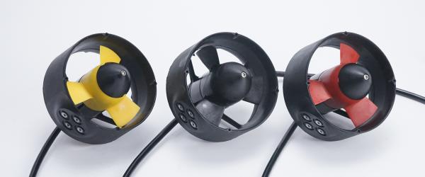
Understanding fluid dynamics is critical for marine engineering. The way water flows through and around a propulsion unit determines its efficiency. We must examine how these two architectures manage hydrodynamic resistance.
Floating ball housings adapt naturally to cross-currents. When an AUV moves laterally, the articulating head can pivot. This rotation presents the smallest possible surface area to the oncoming water. It maintains a lower hydrodynamic profile. This dynamic alignment reduces drag coefficients significantly during complex maneuvers.
Fixed thruster housings face distinct disadvantages here. They induce heavy parasitic drag during non-axial movement. Imagine an ROV strafing sideways. The fixed nozzles act as rigid cylinders blocking the current. They catch water and create massive turbulence. This turbulent wake increases the battery power required to maintain lateral speed.
Cavitation occurs when local water pressure drops below its vapor pressure. Bubbles form and violently implode against the propeller. This process destroys blades rapidly. We must evaluate how propellers behave inside a fixed nozzle versus an articulating ball housing.
Fixed Nozzle Optimization: Engineers design fixed Kort nozzles to align perfectly with expected inflows. This unidirectional alignment maximizes pressure recovery. It keeps the cavitation threshold extremely high.
Floating Ball Risks: Articulating angles disrupt inflow severely. When the housing pivots aggressively, water enters the propeller at an oblique angle. This flow separation can induce premature blade cavitation.
Shielding Requirements: Floating setups require advanced dynamic fluid modeling. We must design adaptive inlet shields to prevent this boundary layer separation.
We measure thrust retention in kilograms of force (kg/f). How much power do you lose when executing a complex maneuver? A floating joint points the entire thrust column in the desired direction. It delivers nearly 100% of its generated force along that specific vector.
Conversely, fixed systems achieve maneuvering through differential thrust. They use arrays of thrusters mounted at 45-degree angles. This layout inherently wastes energy. Two thrusters pushing diagonally oppose each other slightly. This geometric inefficiency results in measurable cosine thrust losses. A single floating Underwater Thruster retains superior absolute efficiency during angled movements.
Theoretical performance means little if the system fails underwater. The deep ocean presents an unforgiving operational environment. We must compare the mechanical resilience of both architectures.
Hydrostatic pressure crushes delicate components. Maintaining seal integrity forms the biggest challenge for articulating systems. A floating ball joint requires dynamic O-rings or sophisticated lip seals. These seals must prevent water ingress while constantly sliding against the spherical housing.
High hydrostatic pressure squeezes these dynamic seals. At 3,000 meters, the pressure exceeds 300 atmospheres. This extreme force increases sliding friction drastically. The seals wear out quickly under continuous articulation.
Fixed thrusters generally offer much higher depth ratings. They utilize simple static seals. Engineers rely on solid epoxy potting to protect the motor windings. Fixed brackets have no dynamic gaps facing external pressure. Their simplicity translates directly into superior deep-water reliability.
Marine environments are dirty. Vehicles operate in sand, silt, and thick bio-fouling. We must assess how vulnerable each design is to environmental contamination.
The floating ball gap presents a critical vulnerability. Silt and marine growth can lodge between the spherical housing and the socket. This debris creates mechanical binding. It increases friction and overworks the articulation actuators. Severe bio-fouling can jam the joint completely.
A rigid, fixed-mount Underwater Thruster provides distinct self-clearing advantages. It has no narrow external crevices. High-velocity water flushes directly through the open nozzle. It washes away sand and prevents silt accumulation naturally.
Brushless DC (BLDC) motors generate significant vibrational loads. These vibrations transfer directly to the vehicle frame. Differences in mounting architectures change how vehicles absorb this stress.
Fixed mounts transfer vibrations rigidly. The chassis absorbs the harsh frequencies. This requires heavy-duty frame reinforcement. Floating ball mounts contain intermediary gimbal structures. These joints often dampen high-frequency vibrations. However, continuous vibration can accelerate fatigue cracking within complex multi-part gimbals.
Failure Mechanism | Floating Ball Architecture | Fixed Thruster Architecture |
|---|---|---|
Seal Degradation | High wear due to dynamic friction under pressure. | Low wear; relies on static seals and solid potting. |
Debris Jamming | Vulnerable; sand/silt lodges in articulating socket. | Highly resistant; open nozzle design is self-clearing. |
Vibration Fatigue | Gimbal parts susceptible to micro-fractures. | Requires heavy vehicle frame reinforcement. |
Bio-fouling | Limits articulation range if not cleaned constantly. | Minimal impact on structural integrity. |
Integrating propulsion into a robotic framework requires advanced software and hardware alignment. The mechanical complexity of your choice dictates your software engineering burden.
Floating ball setups demand highly advanced control systems. They require complex PID tuning algorithms. Your software must manage dynamic thrust vectors in real-time. The vehicle must calculate pitch, yaw, and thrust intensity simultaneously for a single unit. This requires high-resolution rotary encoders. You need active control surfaces to stabilize the fluid dynamics. The computational load on the main flight controller increases significantly.
Fixed thrusters rely on simpler logic. They utilize proven differential thrust mapping. The software simply throttles individual motors up or down. The mathematical matrices required to govern an eight-thruster fixed array are widely standardized. They demand far less bespoke programming.
Equipment lifespan varies drastically between architectures. Maintenance teams must account for these mechanical realities.
Dynamic Seal Lifecycle: Floating joints require frequent teardowns. Technicians must replace worn dynamic seals regularly. The constant friction degrades elastomers quickly.
Static Seal Lifecycle: Fixed mounts operate indefinitely on factory potting. They rarely require seal replacements unless physically breached by heavy impact.
Component Wear: Replacing a gimbal mechanism involves recalibrating internal sensors. Replacing a fixed bracket requires only a wrench.
Scaling a system introduces distinct physical limitations. Consider moving from a 7kg thrust requirement to an 86kg commercial-grade requirement.
Scaling a fixed Underwater Thruster is straightforward. You increase the stator size and thicken the mounting bolts. Scaling a floating ball system is exponentially harder. An 86kg thrust output generates massive torque. Designing a spherical joint to articulate smoothly under 86kg of lateral force requires massive, heavy actuators. The gimbal structure becomes impractically large for many vehicle frames.
Choosing the correct architecture requires strict alignment with mission goals. Neither design solves every problem. You must evaluate your operational priorities carefully.
We recommend floating ball configurations for highly specialized, agile platforms. They excel in environments demanding extreme precision.
Agile Inspection AUVs: Vehicles mapping complex coral reefs benefit from dynamic vectoring. They can glide smoothly while aiming sensors.
Omnidirectional Hovering: Missions requiring complex, smooth hovering in tight spaces. For example, offshore rig internal inspections. They allow AUVs to maintain heading while fighting localized eddies.
Hydrodynamic Optimization: Long-range gliding vehicles. They retract or align the thruster housing to eliminate parasitic drag during coasting phases.
We recommend fixed architectures for heavy-duty, industrial applications. They thrive where raw power and survival define success.
Heavy Work-Class ROVs: Vehicles requiring maximum bollard pull. Fixed units handle the immense torque needed to drag heavy tethers.
Long-Endurance Operations: Applications where maintenance is restricted. If reliability is the sole metric, you must eliminate moving joints.
High-Debris Environments: Trenching, dredging, and seabed sampling operations. Fixed setups ignore sand clouds and power through heavy silt.
Navigating the propulsion landscape requires careful analysis. We must reiterate that neither design is objectively superior. The choice hinges entirely on the balance between agility and ruggedness. Floating ball designs unlock unprecedented maneuverability. They reduce parasitic drag through dynamic flow alignment. However, they introduce vulnerabilities concerning dynamic seals and debris ingress.
Fixed axial designs offer unmatched reliability. They deliver raw unidirectional power without mechanical complications. They survive extreme depths and heavy silt environments. We encourage engineering teams to model their specific hydrodynamic drag and thrust requirements carefully. You should perform software simulations before committing to the mechanical complexity of a floating ball system.
Your vehicle’s survival depends on this choice. We urge you to review comprehensive product spec sheets. Request a thrust-curve data package to analyze cavitation thresholds. Consult with your application engineering team for a custom analysis tailored to your depth and deployment parameters.
A: It depends on the operational phase. A floating ball thruster draws extra power to operate its articulation actuators. However, it saves significant battery life during lateral maneuvers by aligning with the current. This reduces parasitic drag. Overall, floating systems offer better hydrodynamic efficiency but require active control power.
A: A fixed model generally provides higher absolute forward thrust. It benefits from optimal structural alignment and highly tuned, unidirectional nozzles. Floating models experience minor axial thrust losses during severe articulation. Water entering at oblique angles reduces propeller efficiency slightly compared to rigid setups.
A: Fixed mounts consistently achieve deeper ratings, often exceeding 6,000 meters. They rely on static epoxy potting. Floating seals face severe physical limitations. Extreme atmospheric pressure crushes dynamic O-rings, creating massive friction. This restricts most articulating joints to shallower commercial depth ratings.
A: Yes, but it requires multiple units. Engineers use multi-thruster arrays, such as 6 or 8 thruster configurations. They mount these units at angled vectors. By applying differential throttle logic, the vehicle achieves omnidirectional control. This mimics floating joint maneuverability without relying on fragile moving parts.


